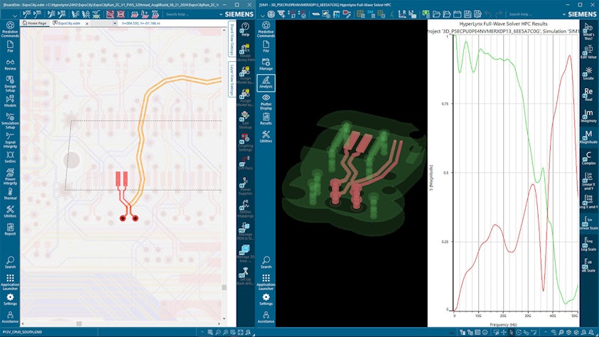
When full-wave solvers are used as part of system-level analysis, the full interconnect is normally too large to be practically solved with a 3D solver. That means that interconnect gets partitioned into sections that require a 3D solver (breakout regions, vias and blocking caps), sections that can be accurately described with trace models, and sections represented as S-parameter models (often connectors and IC packages). This is known as "cut and stitch" solving - the interconnect is "cut" into sections that are each modeled individually, then the pieces are "stitched" back together to create an end to end channel model for system level analysis.
The cut and stitch method maximizes solving efficiency because the size of the areas solved with 3D simulation are limited to critical signal areas and their respective return paths. Outside those areas, representing the signal with a trace or connector model is far more efficient from a compute time and resource standpoint. The challenge with the cut and stitch method is managing all the details correctly - for example, each 3D area needs to be large enough to ensure Transverse Electro Magnetic (TEM) behavior at the port boundaries. This means that the area will include some portion of the signal trace, and the trace length modeled as a transmission line will need to be adjusted to reflect the portion of trace already included in the 3D area. That 3D area also needs to include the signal's return path, so ground stitching vias and an adequate buffer distance also need to be considered when creating the area. Normally, this process is done by hand, requiring considerable user expertise. This vastly limits the number of users who can perform the analysis, and the number of signals they can practically analyze.

Automated post-layout channel model creation
HyperLynx automatically creates post-layout channel models based on requirements for the protocol being analyzed. Users simply select the signals they want to analyze, and HyperLynx does the rest:
- The built-in DRC engine is used to automatically identify sections of the interconnect that require 3D modeling.
- HyperLynx BoardSim creates the appropriate setups for 3D simulation and sends them to the full-wave solver.
- The full-wave solver models the 3D areas to the required frequency and creates models for SI analysis. These models include port metadata that indicates how they should be connected within the full channel model.
- BoardSim combines the models from the 3D simulator with trace and connector models to create a model that represents the channel.
- BoardSim then runs protocol-aware SI simulation (typically SerDes or DDR analysis) to establish operating margins at the system level. This tells the user which signals pass, which fail and by how much.


