Rigid-flex PCB design

Rigid-flex PCB design demands sophisticated PCB design software that can ensure first-pass success by enabling stack-up definition, including unique stack-up styles, PCB bend-areas, region rules such as vias, trace, and plane types, & design visualization in an integrated 2D/3D environment.

What is rigid-flex PCB design?

Rigid-flex PCB design is a hybrid circuit board configuration that combines both rigid and flexible materials, allowing the board to bend or flex while maintaining structural integrity and electrical connectivity.

Why is rigid-flex PCB design important?

Space efficiency

Rigid-flex design allows for three-dimensional layouts, enabling more compact and space-efficient designs compared to traditional rigid PCBs.

Reduced weight

Rigid-flex PCBs are lighter than traditional PCBs with connectors and cables, making them suitable for applications where weight is a critical factor.

Design flexibility

Rigid-flex PCBs offer greater design flexibility, allowing engineers to create shapes and configurations that were previously difficult or impossible with rigid PCBs.

Key features of rigid-flex PCB design using Xpedition

Multiple board outlines
With Xpedition, all you need to do to create a rigid-flex design is to draw the multiple board outlines and assign layer stack-up to each. Each board outline is given a name so that it can be easily identified when outlines overlap partially or completely.

Bending and folding
The key reason for making a flex design is so that it can be bent or folded. Xpedition includes a draw object, called a “bend area,” the location of which defines where the bend happens.

Route along curving boards
When you have a curving flex cable and as many signals that can fit with a tight squeeze, you need a special routing algorithm that can follow the contour of the board outline and automatically insert all the signals required. In Xpedition, all curved traces use true arc primitives.

Design Rule Checking (DRC)
Xpedition is unique in its ability to generate and maintain these dynamically and have a DRC that reports if a tear drop fails.

Signal and Power integrity analysis
Co-developed with Xpedition for analysis of flex-rigid designs, HyperLynx understands how interconnects pass different stack-up scenarios and applies proper modelling in each section. You can use this analysis to ensure a functioning design with complex stack-up.

Dive deeper into this topic

Rigid-flex blog image 1280x720 2-1

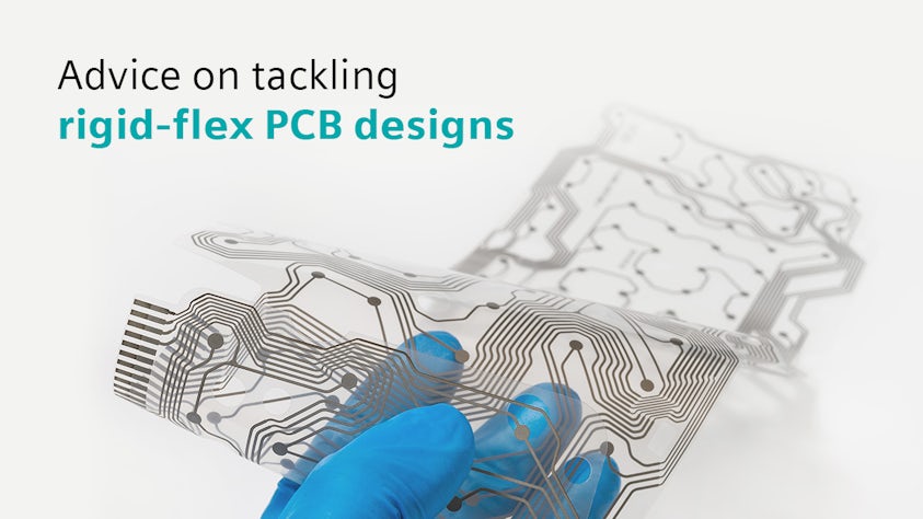
Read more about rigid flex PCB design in our blog: Advice on tackling rigid-flex PCB designs.

Frequently asked questions about rigid-flex PCB design

What is a rigid PCB?

A rigid PCB is a type of PCB that is made from a solid substrate material that does not bend or flex easily. These boards are commonly used in electronic devices where there is no need for the board to conform to a specific shape or bend during operation. The substrate material for rigid PCBs is typically made of fiberglass reinforced epoxy laminate, although other materials like phenolic resin or polyimide can also be used.

Rigid PCBs are widely used in a variety of electronic applications, including computers, televisions, smartphones, and industrial equipment. They provide a stable platform for mounting electronic components like resistors, capacitors, integrated circuits, and connectors. The traces that connect these components are typically made of copper and are etched onto the surface of the board.

What is a flexible PCB?

A flexible PCB, or Flexible Printed Circuit Board, is a type of printed circuit board that is made from flexible materials that allow the board to bend, twist, or flex without damaging the components or the circuitry. These boards are often used in electronic devices where space is limited, or where the board needs to conform to a specific shape or contour.

The substrate material for flexible PCBs is typically made of polyimide or polyester film, although other flexible materials like PTFE (Teflon) can also be used. The conductive traces on flexible PCBs are usually made of copper, and they can be either etched onto the surface of the flexible substrate or embedded within the layers of the substrate.

What are the advantages of rigid flex PCBs?

Flexible PCBs offer several advantages over rigid PCBs, including:

  • Space-saving: Flexible PCBs can be folded or bent to fit into tight spaces, making them ideal for compact electronic devices.
  • Weight reduction: Flexible PCBs are generally lighter than rigid PCBs, which can be beneficial for portable or wearable devices.
  • Improved reliability: The flexible nature of these boards can reduce the risk of mechanical stress or fatigue on the solder joints and components, leading to improved reliability and longevity.

Why does a flexible PCB need stiffeners?

Stiffeners are often used with flexible PCBs to provide additional support and rigidity in specific areas of the board. They help to support heavier or larger components, distribute mechanical stress from connectors more evenly, reinforce the board against vibrations and shocks, aid in heat dissipation from heat-generating components, and facilitate easier handling and assembly during manufacturing. Overall, stiffeners enhance the mechanical strength, reliability, and longevity of flexible PCBs, especially in applications where the board is subjected to mechanical stress or where heavier components are utilized.

Is it necessary to have stiffener where we have component on flex in every case?

It depends on the method of assembly, for example if you use a fixture you would not need a stiffener.

What materials are used in a rigid flex PCB?

Rigid-flex PCBs combine rigid and flexible materials to achieve their unique structure and functionality. The rigid sections typically use materials like FR-4, polyimide, or specialized Rogers or Teflon-based laminates, while the flexible sections employ flexible substrates such as polyimide (Kapton) or polyester (PET). Conductive traces are made of copper foil, laminated onto the substrates with adhesive layers. Adhesive and coverlay materials bond and protect the circuitry, and stiffeners may be incorporated for additional support.

The selection of materials depends on factors like mechanical flexibility, thermal performance, electrical properties, and environmental considerations, ensuring reliable and efficient operation in various electronic applications.

What are the differences between flexible and rigid flex PCB?

Flexible PCBs consist entirely of flexible materials like polyimide or polyester, offering greater design flexibility and are commonly used in applications requiring mechanical flexibility, such as wearables and medical devices. In contrast, rigid-flex PCBs combine rigid sections made of materials like FR-4 or polyimide with flexible sections using flexible substrates, striking a balance between design flexibility and structural integrity. Rigid-flex PCBs are utilized in applications that demand both rigid and flexible elements, like smartphones, industrial equipment, and aerospace systems.

While flexible PCBs are generally simpler and more cost-effective to manufacture, rigid-flex PCBs can be more complex and expensive due to the integration of rigid and flexible sections, requiring careful design and material selection to ensure long-term reliability and durability.

Is a rigid flex PCB expensive?

Rigid-flex PCBs can be more expensive compared to traditional rigid or flexible PCBs due to their complex design, specialized materials, and manufacturing processes. The combination of rigid and flexible sections, as well as the integration of different materials like polyimide, FR-4, and copper foil, can increase the overall production costs. Additionally, the design and assembly of rigid-flex PCBs may require specialized equipment and expertise, further contributing to the higher cost.

However, it's essential to consider the overall benefits and advantages that rigid-flex PCBs offer, such as space-saving, improved reliability, reduced assembly complexity, and enhanced design flexibility. In many applications where these benefits are critical, the higher upfront cost of rigid-flex PCBs may be justified by the long-term performance, reliability, and cost savings achieved through optimized design, reduced assembly time, and minimized component count.

How much maximum copper thickness can we use for the flex region of a rigid flex PCB?

Typical max and material availability is 3 ounces. At the end you need to also make sure that the functional bend requirements are met.

Is a hatched ground plane recommended over a solid plane to keep the flexibility?

It is more flexible but not a requirement. It depends on if you are making a tight bend radius and how thick the flex area is.

Can coverlays be used as shielding against noise?

No, you usually need silver paste or silver film on top of the coverlayer with access holes in the coverlayer to the ground, so the silver makes contact with the ground. Then another coverlayer over the silver to protect it.

Rigid-flex PCB design resources