Connector management
Xpedition minimizes the effort to add, manipulate and update connectors with on-the-fly creation of parameterized connectors (compliant with IEC standards) with connector expansion and pin number modification by using a simple stretch command. The high degree of automation enables designers to create and modify connectivity using generic connectors without concerning themselves with the actual physical details of the connector.
Connector management enforces a “correct by design” approach, eliminating connection errors up front and anytime during the overall system design cycle, and it provides automated mating and pin pairing of connectors.
Connectors are intelligently managed by:
- Synchronization between the physical PCB, cable implementation and the system design data
- Automated choice and assignment of possible mated connectors
Multi PCB and cable integration
After the designer creates associations between logical boards and PCB designs at the system level, the system designer can start to synchronize the content of logical boards and associated PCB schematics using a bi-directional process. A synchronization assistant provides the list of changes, a preview of the logical board definition and color coding that clarifies synchronization status of particular objects. This window provides a multitude of tips to help solve problems and to provide useful information for new users. Because the PCB schematic is synchronized with associated logical boards, the PCB schematic contains connectors and system level blocks that are, in effect, hierarchical blocks.
Therefore, board designers can push into these blocks and define logic on the underlying schematic to realize each specific function of the system.
The synchronization process is not automatic but is controlled and well managed so that the synchronization tasks are executed only by responsible designers. The software tracks changes between boards and their content, connectivity between the boards and pin-to-pin relationships between connectors.
Integrated cable design
In some multi-board systems, interconnection between boards and other system components (such as sensors) is implemented by cabling. Logical system connectivity can be simply partitioned into multiple cables. Each logical cable requires physical representation. The tool has a variety of features to automate selection of parts by automatically adding wires, multicores, terminals, tapes, and all other cable components for ready-to-manufacture cable designs, including bill-of-materials and manufacturing drawings. Automatic calculation of quantities (e.g., 'true' manufacturing wire lengths) ensures correct-by-construction cables. Tight integration between ECAD and MCAD environments is essential for an efficient system design process. Mechanical designers can collaborate with cable designers by exchanging critical design decisions that impact each other’s design.
Dive deeper into this topic
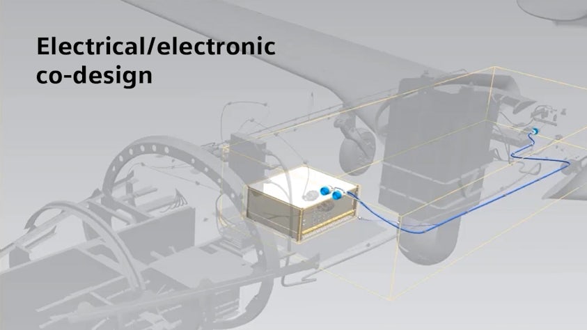
Electrical/electronic co-design is a powerful design approach. We now have the capability to utilize the digital virtual world along with today’s automation to increase our design efficiency and optimization in successfully designing today’s complex systems. Read more in our electrical-electronic co-design blog or listen to our podcast on electrical-electronic co-design.